
Its been a while since I worked on a large personal project. Ive been mostly getting by with small side projects, or working on my professional work instead. So when I was contacted to help a fellow maker model their way out of a problem, I thought it a good idea to lend my “expertise” towards their project. I feel like ive been doing alot of this “consulting” style of work recently, and its been a refreshing change of pace. Watching other peoples ideas flourish, and knowing I gave a little push to help the magic happen, always satisfies me!
To set the stage, I will introduce our maker of the hour, Mr Tomasz of “Mellow Labs” fame. Mellow is somebody who I have been watching for about a year now, as I found his projects to be creative and charming. I have a habit of brushing off the style of “small” projects that Mellow does, and so I enjoy seeing what he has come up with each week, as he tends to cover a lot of ideas I would never think to work on myself.
The project on the agenda this time was an iteration of his nozzle camera for his printer. Ive seen people install these before, but had never considered one myself for the reasons above. His existing design used a 480p endoscope and was loosely mounted with a custom bracket to his Prusa printer. This setup was good for streaming, and producing short form content, but the low resolution (and presumably dodgy mounting mechanism) meant that an upgrade was needed. To accomplish this, it was back to the drawing board to design a new camera and mount. Mellow purchased a new camera through a certain large online retailer, boasting a dazzling 720p, whilst remaining small enough to be mountable to the printer with a custom bracket.
Now this is where I come in! Across my interactions with Mellow (usually on his fantastic little livestreams) ive always had one minor issues with the way he goes about his projects. Being a massive fan of parametric and history-based CAD workflows, seeing Mellow rely on so called “direct modelling” without using the timeline always resulted in suitable teasing and sarcastic mockery from me. This mustve given me a reputation, as a couple of days into 2025, I found a neat message sitting in my Discord DMs.

I was overjoyed! Thrilled even! Finally, I could put my skills to use and prove myself in the dark world of engineering, and help a good person make good things in the process! I immediately put down all of my professional work (that I was supposed to be doing then) and cracked open Fusion to understand the challenge before me. Mellow had sent me some explainers, including sketched images, and worded descriptions, some of which you can see below, but most importantly, attached to the DM, was a STEP file!
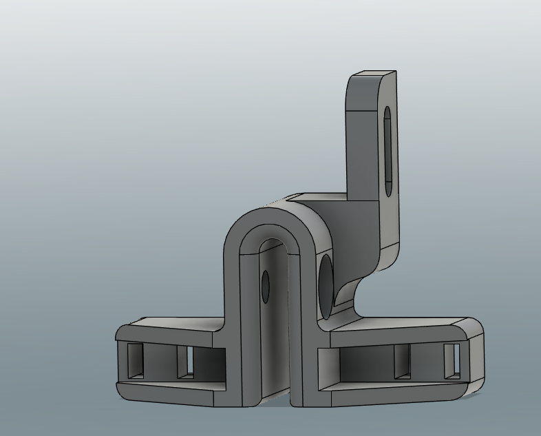
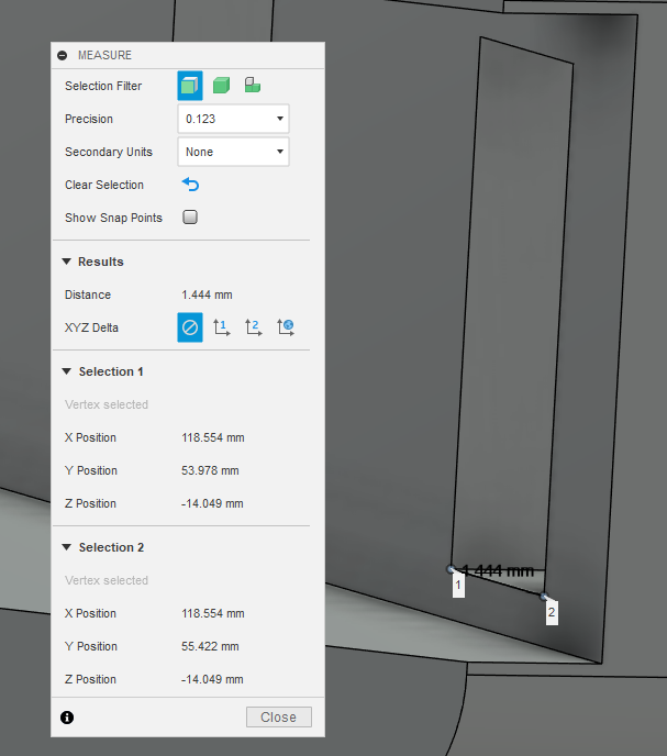
Once I had loaded up the model, I was immediately presented with a nice little design for the camera. It was clear that Mellow had a good idea of what was needed, and the overall design was very good, but it was gonna need some work to bring it to the level that I would personally consider to be “finished”. Firstly, alot of the measurements were to, what I would consider, a nonsenical degree of accuracy. I know full well my printer is unlikely to care about +/-0.01mm, and honestly even if it did, I dont! As a rule of thumb I will never go past 1 decimal place, unless something is a half (like 1.65mm), and I will instead round up or down as I see fit (eg, 1.61 becomes 1.60 and 1.783 becomes 1.8). I applaud Mellow for his dedication to accuracy, but the inclusion of 3 decimal places from the chinese special calipers (of which every engineer secretly holds in great esteem) is PROBABLY unneccesary (I dont even think my calipers are accurate to 0.1mm….).
Whilst checking for these strange numbers, I also noticed some slight modelling inaccuracies. I dont mean this in a negative way, as they were incredibly small things that only sad people like me would search for, but it bugged me enough to want to fix it. I know from watching him, that Mellow does not use the snap to grid function, whereas I am very much a snap to grid person (A nice analogy for ADHD vs Autism eh?), so a couple of sections of the model didnt line up in a way I personally would consider satisfying and “proper”.
The final issue I noticed, was the lack of, well, a timeline. Now you could probably re enable design history, and fudge in some repairs to get a blank canvas, that can then have some parametric sketches added, but this seemed like a lot of effort! The rational option? Give up and start from scratch! I love modelling things like this, and secretly, the idea of going from scratch seemed incredibly fun as both a challenge and exercise to me! It would also let me sort out some of the strange decimals, and draw up sketches in a way that would make parameterizing easier. I basically just broke the part down into composite Front, Plan, and Side view to form the basic shape, and then added the cutouts for various things after the fact seperately. I could go into great lengths on small things I do when 3D modelling, but nobody wants to read that!
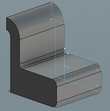
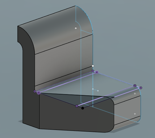
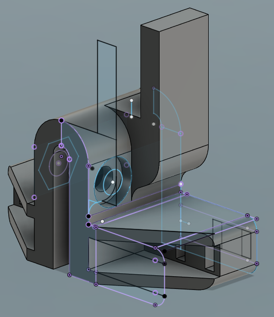
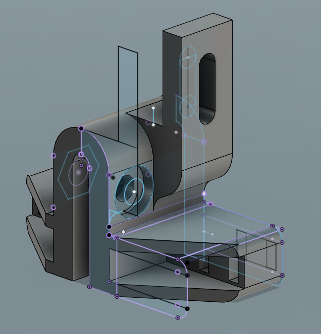
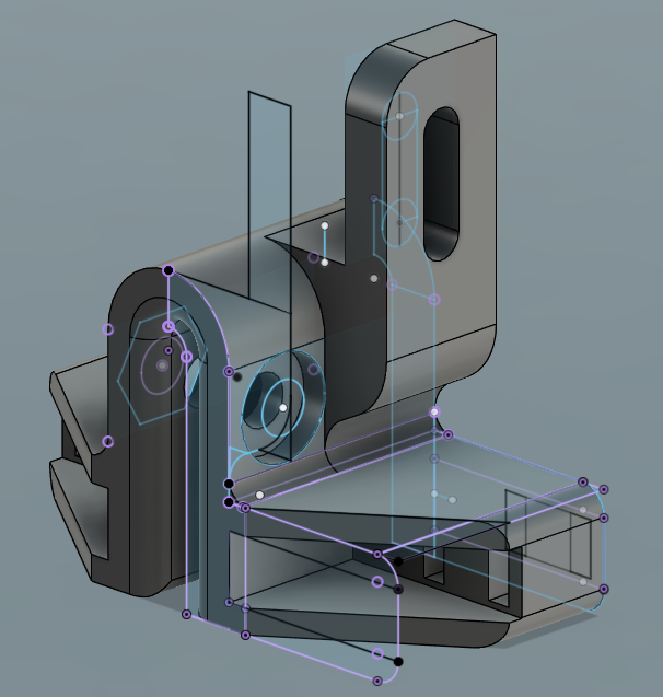
I always start with the primitive shapes, in this case the complicated one first, of which I can then slice out the different angles and cuts (using some classic engineering guesstimation and measuring). I kept referring back to the original model using projections to ensure everything was matching (relatively) perfectly. Alot of times, if things line up naturally, and look right, they are perfect!
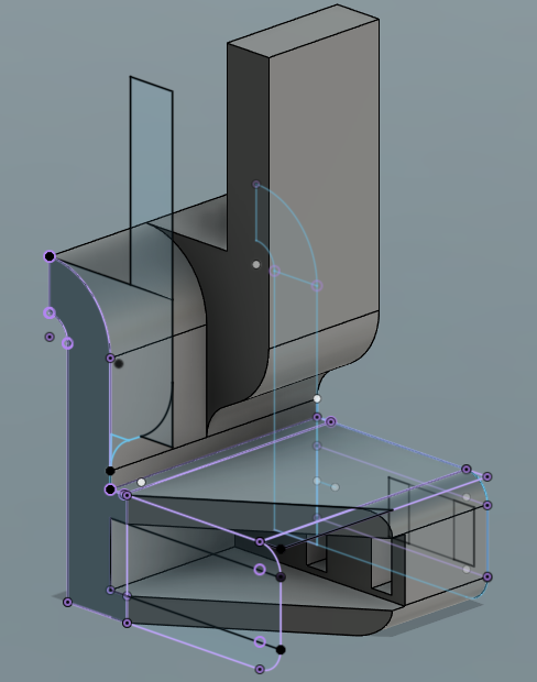
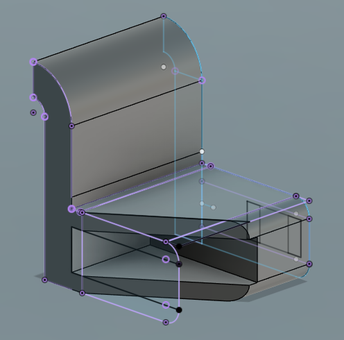
Working in halves here saved me 50% of the sketching work (MATH!), but introduced the problem that the sticky up bit would be doubled! This however was easily rectified by simply detaching it from the model, and later recombining it after the mirror had already occured.
Leaving the fillets to the end is a good little tactic that allows a satisfying and quick jump from “prototype” to “final model” and ensures that your fillets dont cause craziness with any extrusions or sketches in places. After I got everything working, it was time to finally do what I was actually asked, and do some parameters!

Now this is where I admit something, I didnt actually know what proper parametric design was when I made this… I knew that you could use “sketch dimensions” and put math inside measurement boxes to make measurements variable, but I had never progressed past that. Turns out, after some googling, that I actually had been doing parametric design the whole time! After simply creating a variable in the parameter menu, you can just input this variable in place of measurements! Having already set up all the constraints (which are black magic to me, and mostly involve guesswork and prayers) and the sketch dimensions, it was just a matter of switching out the numbers with text boxes saying “change 2.6mm to edit the size” to just use variables!

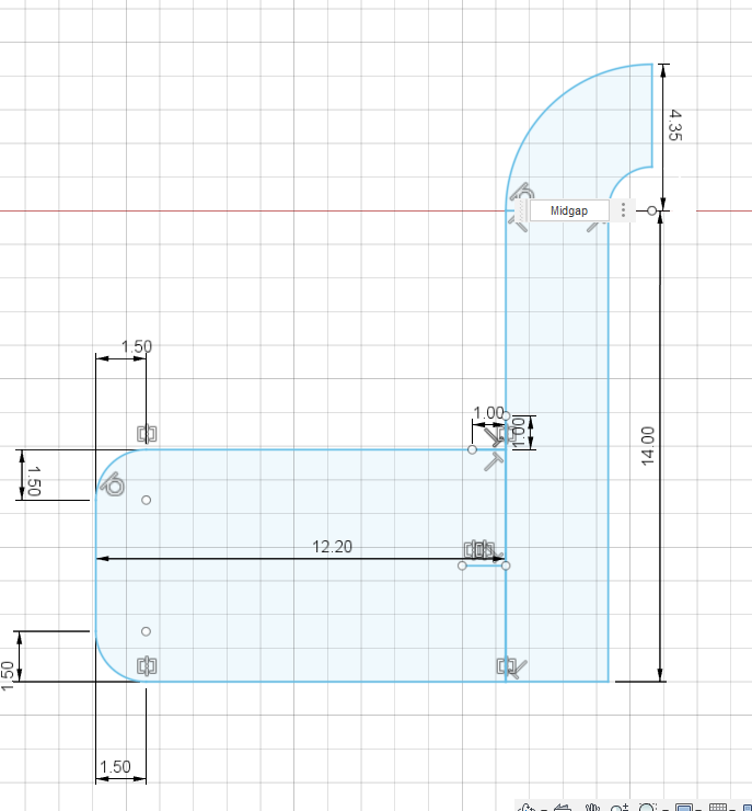
Doing the middle gap was easy, and just required one straight variable, but the LED holder section would put up MUCH more of a fight with me.
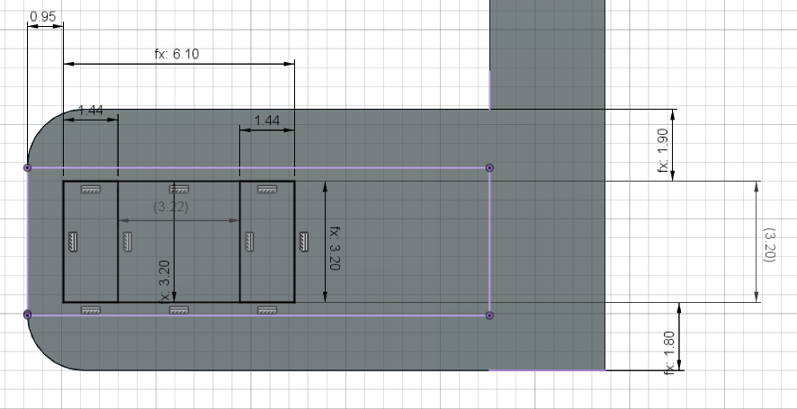
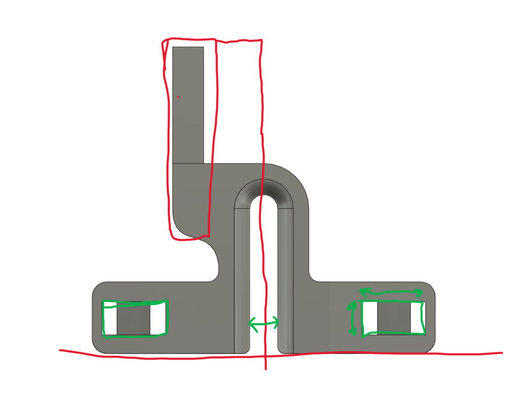
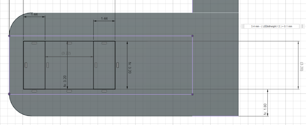
In Mellows original design, the distance from the edges of the LED cutout and the edges of the mount, was not the same. The top section was 1.90mm whilst the bottom was 1.8. I considered making both 1.85, but because of strange rounded measurements in other places, it would throw ALL the math off if I did. This meant I had to compensate within the parameters to make everything work perfectly. For example, to keep everything the same distance from eachother as the LED holes are scaled up, I had to change both the edge distance, and the height of the LED holes themselves, editing just the height of the holes would result in them going over the cut out area, or leaving a huge useless gap when made smaller.
Invoking some basic algebra (see what I meant about it being a pain) I formed an equation that would calculate the correct distance based on the inputted LED hole height. If you dont want to see me explain some (relatively) simple algebra, feel free to skip over the next section entirely!
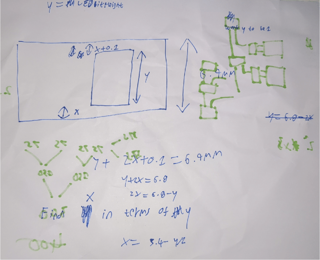
I start by drawing a diagram (unfortunately on a sheet of paper with bleeding through green felt tip from my Satisfactory game, doh!). I am not some sort of super math person, and I work alot better, and make better links/connections, when I can visualise what I am doing. I set 2 variable, one of Y (which represents our user defined height) and one of X (the calculated height). Notice how the top x is x+0.1 to account for the fact its technically always 0.1mm mre than the other value! This is incredibly important as the math will otherwise not work!! I start by taking the max possible length so we have some actual constraints to work with, which is where the 6.9mm comes from. We know that the sum of x, x+0.1, and y, must always equal this 6.9mm. If it does, then everything stays perfectly in line and works and is lovely. We can write that as y+2x+0.1=6.9mm. Now we have some numbers to work with we can work out what to do. We want to find out how to get x from the users y value, so we need an equation that says “x=”. The first obvious thing we can do is get rid of out 0.1, by subtracting it from both sides. This results in a new equation of y+2x=6.8 (see where this is going?). We can then really do a couple of things, but I would first subtract the y from both sides to remove it from our x portion. This gives us 2x=6.8-y. Now, most people will see here that we have 2x, not x, so intuitively we need to half everything. This gives us x= 6.8/2 -y/2 AKA x= 3.4 -y/2. And boom, thats our equation! MATH OVER.
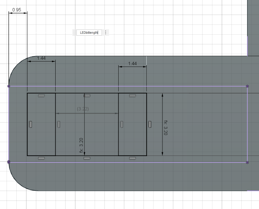
Luckily, parameterizing the height is length is much easier… We can just simply tell Fusion to ensure that the distance from the left wall stays at 0.95mm, and then allow the user to vary the length directly. Any added length will just effectively add to the right side! The 2 squares are locked using some black magic constraints so that they do not disconnect from the walls, and follow them properly. I dont really understand constraints, so the fact it just worked right away saved me a headache…

In the end I was pretty proud of my work, and I think Mellow enjoyed it! The video featuring the new camera will be on his channel in the coming days, and I will make sure to pop a link to it here (its patreon only when I write this). EDIT: Its now up! It was fantastic to play my part in the project, and although I have probably taken the whole “asking a mate for help” thing to a professional extreme by writing a blog post about my work, I do love to write about what Ive worked on, in the same way Mellow enjoys making videos!
Anyway, for now, its back to my professional work, and, with a big thank you to the amazing maker (and general person) that Mellow is, I bid this project, complete!