
WARNING: THIS IS A PRELIMINARY ARTICLE. THIS PROJECT IS NOT FINISHED!!! I INTEND TO UPDATE IT SOON, BUT I WANTED TO GET SOMETHING DOWN BEFORE I INEVITABLY FORGET.
Its been a long time since I felt genuinely passionate and driven to make something. As previously seen, most of my creations are born from neccesity, which can be a fun motivator, but gets repetitive quickly. So to spice things up, lets talk about my newest project: the Lumison!
Part 0: Get Inspired
To start with, lets lay some ground work for inspiration. We can all agree that LEDs are cool, right? And more importantly, RGB LEDs are cool, and in some cases quite dazzling. Ive used alot of “addressable LEDs” in my projects. They are (in my opinion) the easiest, cheapest, and coolest upgrade you can do to a project, immediately taking something from simple design to electronic marvel.
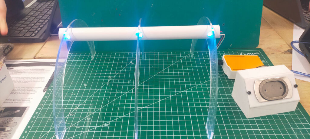
Well theres a cool trick you can do with these LEDs, that I have spent alot of time playing with, to some interesting results. When cast acrylic sheets have light shone into their sides, they will glow in an incredible sci-fi way. I think this looks super cool, and gives projects a real futuristic look, and yet few products actually take advantage of this quirk of light piping. In 2022 I did a project involving addressable LEDs and acrylic panels to create a “corridor of lights”, but it didnt really work out in the way I had intended.
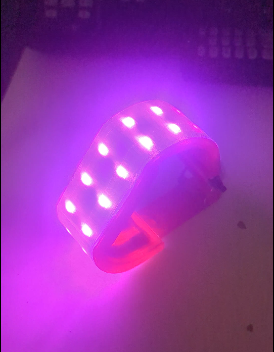
It did however, spur the idea of a sort of light up name badge. Now I quite enjoy making compact, light up, wearable technology, as I find it can really test your CAD, manufacturing, and electronics skills. Ive come up with some real inventive designs in the past to get around the limitations imposed by making something both stylish, and usable.
However, with the 2022 LED badge, it was not to be. I never got the prototype to function above “usable” and ended up scrapping it about a month into the process. There were a couple of attempts to kick start the idea again, but it was a clear a fundemental redesign was needed. The project was not inspiring the joy in me I wouldve liked.
Part 1: Bring The Past To The Present
Nearing the end of october, I decided I had spent enough time without making something. The last major thing I had created was my watch in May, and I missed the feeling of truly making something. And I dont mean just making a case for a product, I meant the whole experience of designing, testing, problem solving, iterating, etc.
I was soon reminded of the LED badge idea. It felt like a good concept to latch onto and focus my efforts, especially with the new skill level I had achieved. Conceptually, everything was solved, but it was the actual nitty gritty fun bit that needed doing, and I was ready to get stuck in. I knew I wanted to properly try out PCB fabrication, and I wanted to learn to SMD solder, and a mass producable, LED badge seemed like a good place to try those skills out. I also knew from before that the internal electronics were the difficult parts. Anyone can make an led light a single color using the internal resistance of a coin cell, but I wanted to do something better, something I could even sell.
My first step was to envision what I wanted. I realised quickly that laser cutting acrylic per customer would be too expensive, and would require more equipment than I currently owned, so I (radically) decided to immediately cut that part out. I did want to keep the edge lit acrylic, as it was the base of the project, so I settled on the idea of it acting more as a front lit light box than the image itself. This meant the user could swap out what image was being displayed, and it would be easier to assemble, a DOUBLE win! I copied the rest of the specification from the original idea, eg, battery powered and easy to use, looks nice, has to fit comfortably on a lanyard, has to be mass producible in my home, must be profitable.
Part 2: The Nitty Gritty
After drawing up the spec and with a rough idea in mind, it was PCB and schematic time!
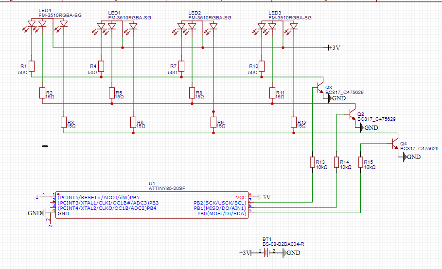
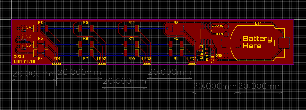
With the aid of the internet, and alot of browsing LCSC for components, I came up with a simple schematic that would led me drive 4 RGB, side lit LEDs from an attiny85. Normally, I would use an Arduino, but I knew the attiny was cheap and low power, and I wanted something professional from outside my comfort zone. For power I picked a coin cell (although this would later be the subject of heavy debate) as it gave 3V, was easily replaceable for the user, and could provide a reasonable 400mAh. The transistors were an after thought, just standard SMD transistors that could do around 500ma of load, way overkill but eh. Each color is driven independently, not each LED, allowing for the whole badges color to change. I also didnt include a button, as the attiny85 supports capacitive touch, adding to the futuristic element! All these features then had to be put onto a board….
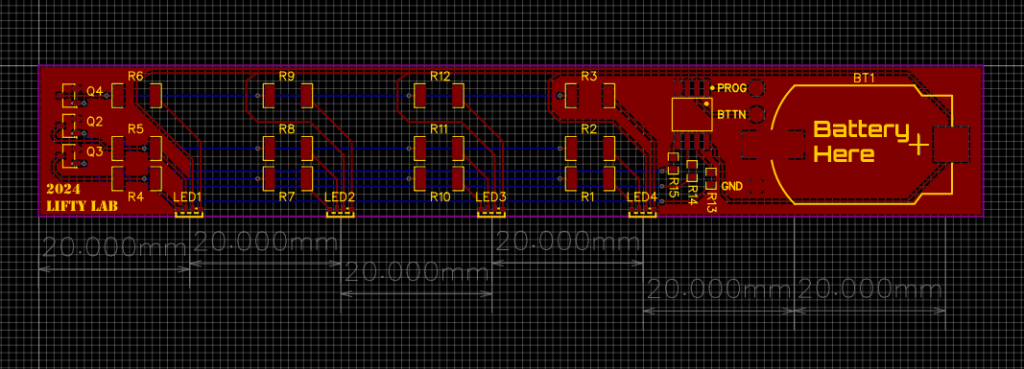
Board design is not something I pride myself on being particularly good at, but I have only ever made one small mistake in 3 PCBs so I trusted myself here. I think I did a reasonable job, although I did mess up and select high power dissipation resistors due to a miscalculation, meaning they take up more space than required. Getting everything to fit neatly in a 20mm space was proably my most impressive feat, although I did have to extend the board from 100mm to 125mm for the battery (this will come up again later).
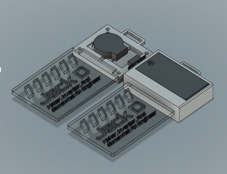
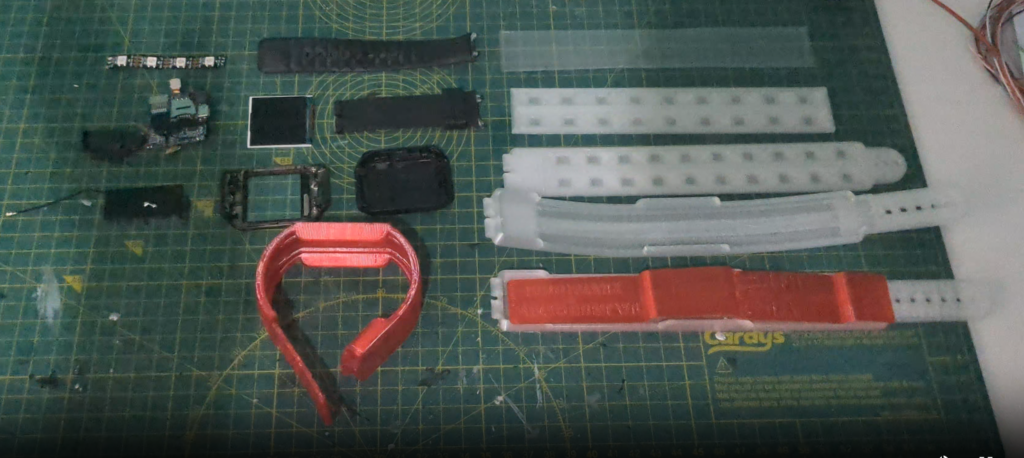
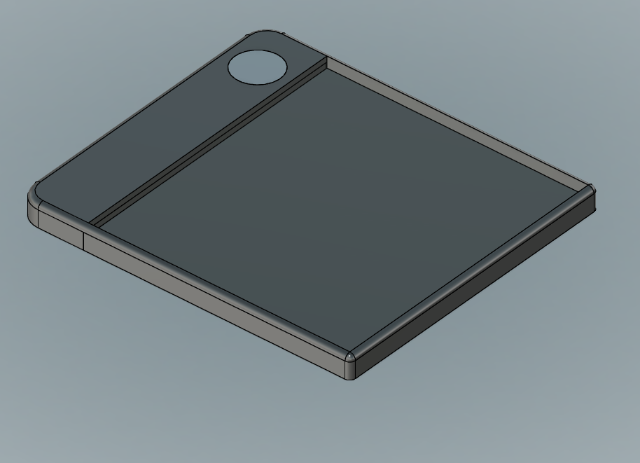
After finalising the boards, having them sent off to the fab, and then ordering the SMD components, it was Fusion 360 time. I pride myself on being confident in CAD, so it was a quick endeavour to mock up a rough idea of what I wanted. I only needed the general size, shape, and feel at first, so there was no point overengineering until the PCB had arrived, been tested, and then finalised. I came up with a design inspired by those light up drawing tablets for kids, with the capacitive button at the top, the battery door on the side, and the main acrylic panel held in the middle with a bracket at the base. Its not exactly the most complex CAD, but it allowed me to visualise how everything would fit inside.
And this is where I am at now. As of 02/11/24, I am waiting on the boards, and cannot progress much further. I have been formulating a second version using AAA batteries but I will wait to reveal that until it has been further developed. Until then, have a good day reader!